Hardware
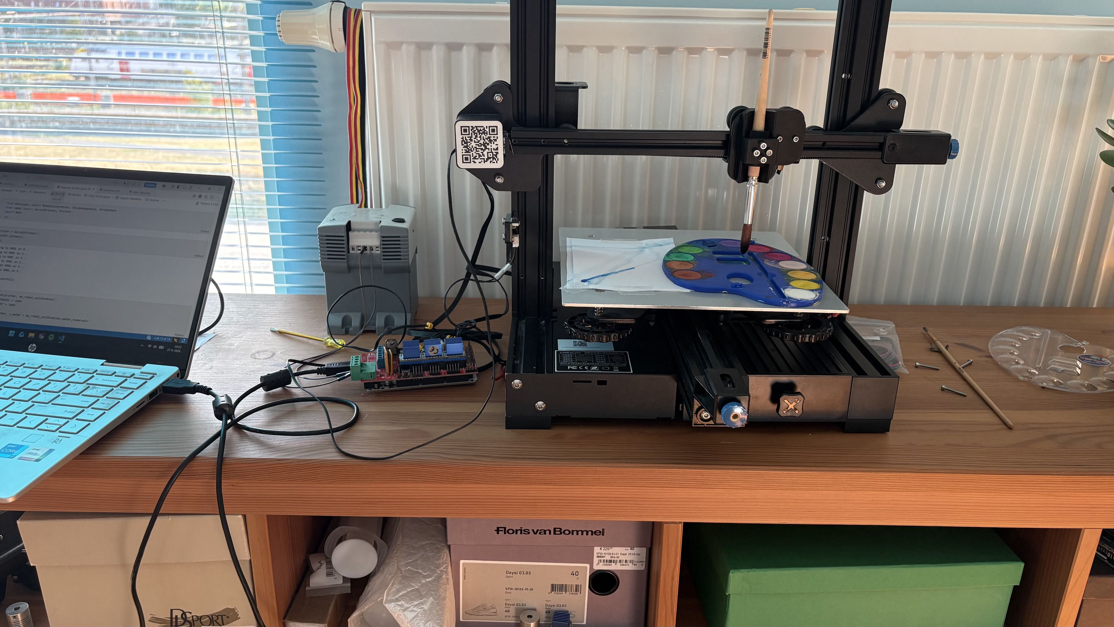
In this chapter we will give a short introduction to our setup. We will discuss the components used and how to install the software.
Overview
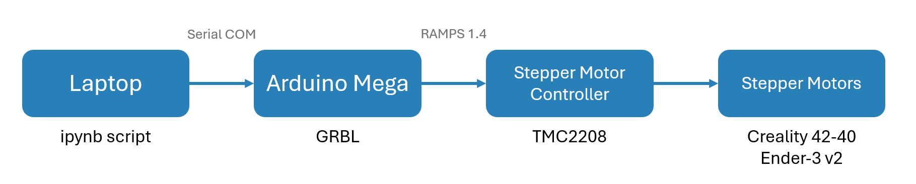
Our computer wants to send instructions to our printer. More specifically, we want to tell the printer precisely which position to move to.
To achieve this, the computer connects to an Arduino using a serial communication (a usb port).
Then we can send very simple command such as G0 X10 Y20 Z30 to move the printer to position (10, 20, 30).
A list of valid commands can be found below.
The arduino then controlls its GPIO pins to tell the stepper motor drivers how often to step and in which direction.
The stepper motor drivers will close the A and B loops of the physical stepper motor itself to make the stepper motors move.
In a later version, we changed the laptop for a Raspberry Pi 4B. See raspberry pi for more details on the configuration.
In order to hold the brush, some parts had to be 3d printed. See 3d prints.
Part list
If one wants to copy our setup, the following parts will definetelly be required.
| Part name | Short Description |
|---|---|
| Arduino Mega 2560 Rev3 | Accepts GRBL commands and interacts with the stepper motor drivers. |
| TMC2208 | The stepper motor driver. |
| Ender-3 v2 | This is the backbone we use for the entire hardware. |
| Creality 42-40 | This can be an alternative for buying the entire printer. |
| 24V 2.5A Power supply | The arduino can not deliver enough power for the stepper motors. |
| RAMPS 1.4 | This board is placed on top of the Arduino, to connect the GPIO pins to the stepper motor controllers. On the board are also capacitors to regulate the voltage. |
This list is a suggestion
The parts in the above list are those that we used in our setup. All of them could be replaced with an alternative. You could, for example, use an Arduino Uno with the Arduino Uno CNC board.
Marlin Software
The Arduino Mega is equiped with the latest Marlin software.
We found it most conventient to upload this using the PlatformIO extension for vscode, altough that is
a personal preference after all.
Some modifications to the Marlin source code were made. You can find the diff file here.
Reload when making changes
When making changes to the configuration file of the Marlin software, the changes will not take place
immediatly after upload. Indeed, the program uses EEPROM to save settings into persistent memory. You need to send $RST in order to reset the settings.
TMC2208
When plugging the stepper motors in the RAMPS shield, they should work right away. It might be necessary to place jumpers on the three pairs of pins on the shield, below the stepper motor to enable microstepping.
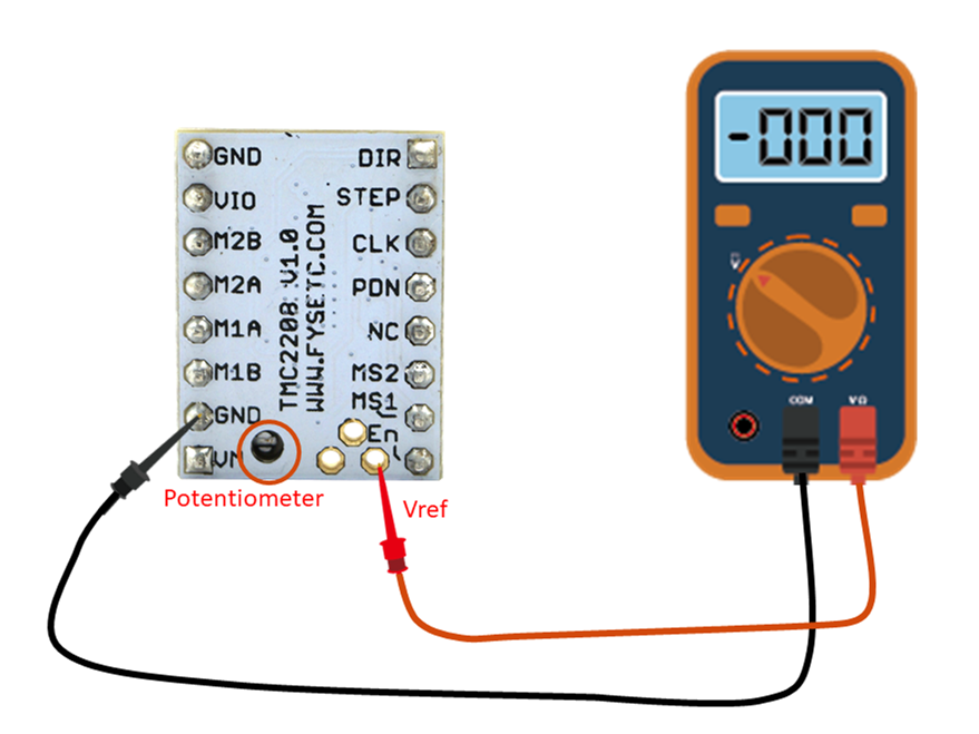
If you want to control your vref voltage with a potentiometer,
see fysetc.
Watch out with high voltage
The potentiometer decides the voltage that goes to the stepper motors. Rotating the potentiometer counterclockwise all the way will blow up the stepper motor controller. We had to find this out the hard way, but you dont have to.
Our stepper motors overheated after extensive use. After turning the potentiometeres clockwise, the problem seemed to be resolved.
Advanced settings
You can also use the uart mode of the TMC2208 chip. See Instructables on how to ebable UART mode. Note that you also have to make modifications to the Marlin software such as setting sthe drivers to TMC2208.
When running M122, Marlin returns all settings of the chip.
Click here to see the serial output.
X   Y   Z   E
Enabled     false   false   false   false
Set current 400 400 400 800
RMS current 718 718 718 1436
MAX current 1012    1012    1012    2025
Run current 12/31   12/31   12/31   25/31
Hold current    6/31    6/31    0/31    12/31
CS actual   0/31    0/31    0/31    0/31
PWM scale
vsense      0=.325  0=.325  0=.325  0=.325
stealthChop false   false   false   false
msteps      256 256 256 256
interp      false   false   false   false
tstep       0   0   0   0
PWM thresh.
[mm/s]
OT prewarn  false   false   false   false
pwm scale sum   0   0   0   0
pwm scale auto  0   0   0   0
pwm offset auto 0   0   0   0
pwm grad auto   0   0   0   0
off time    0   0   0   0
blank time  16  16  16  16
hysteresis
-end        -3  -3  -3  -3
...
Testing Y connection... Error: All LOW
Testing Z connection... Error: All LOW
Testing E connection... Error: All LOW
ok
Commands
Our Marlin software will accept most of the GCODE commands, plus some GRBL-specific commands. We shortly go over the most important commands. See the source for a full list of all commands.
| GCODE command | Description |
|---|---|
G0 / G1 |
Move – Move to a specified position in 3d space. |
G28 |
Home – Do a calibration routine to reset the relative position to the hard limits. |
M114 |
Get position – Prints the current position of the printer in realtime. |
| We wait by taking a picture until the printer has reached a designated position. |
Source: reprap: G-code
The following commands are specific for GRBL, not Marlin. We do no make use of them.
| GRBL Command | Description |
|---|---|
$$ |
View all settings – Displays the current values of all Grbl configuration parameters. |
$# |
View coordinate offsets – Shows the current G54–G59 work coordinate offsets and any programmed tool or probe offsets. |
$G |
View modal state – Displays the active G-code modes (e.g., G21, G90, G54). Helpful for debugging command behavior. |
$I |
Build info – Returns firmware version and any build metadata (optional). |
$H |
Run homing cycle – Initiates a homing routine if homing is enabled in settings ($22=1). |
! |
Feed hold – Pauses motion immediately but safely. Can be resumed with ~. |
? |
Status report – Asks Grbl to send back a real-time status report. Can be sent repeatedly. |
Source: easel: Grbl v1.1 System Commands